Access Serial Port
Jump to navigation
Jump to search
Instructions
- Obtain Futuredial LG5350 Cable USB->Serial cable that uses TTL levels rather than RS232 levels such as which I got for $10 from Radio Shack*
- Chop off the end that connects to the phone (NOT the USB end)
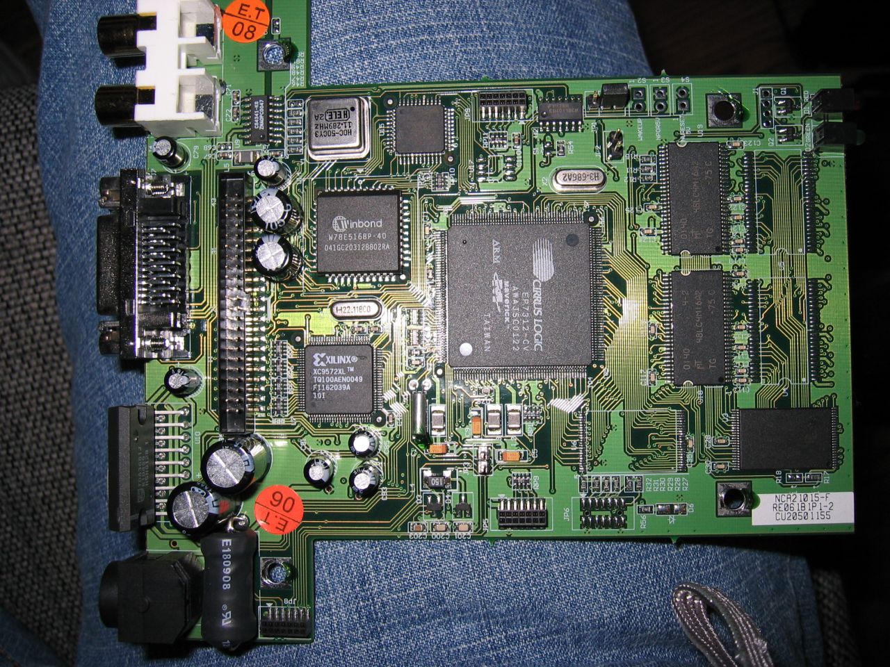
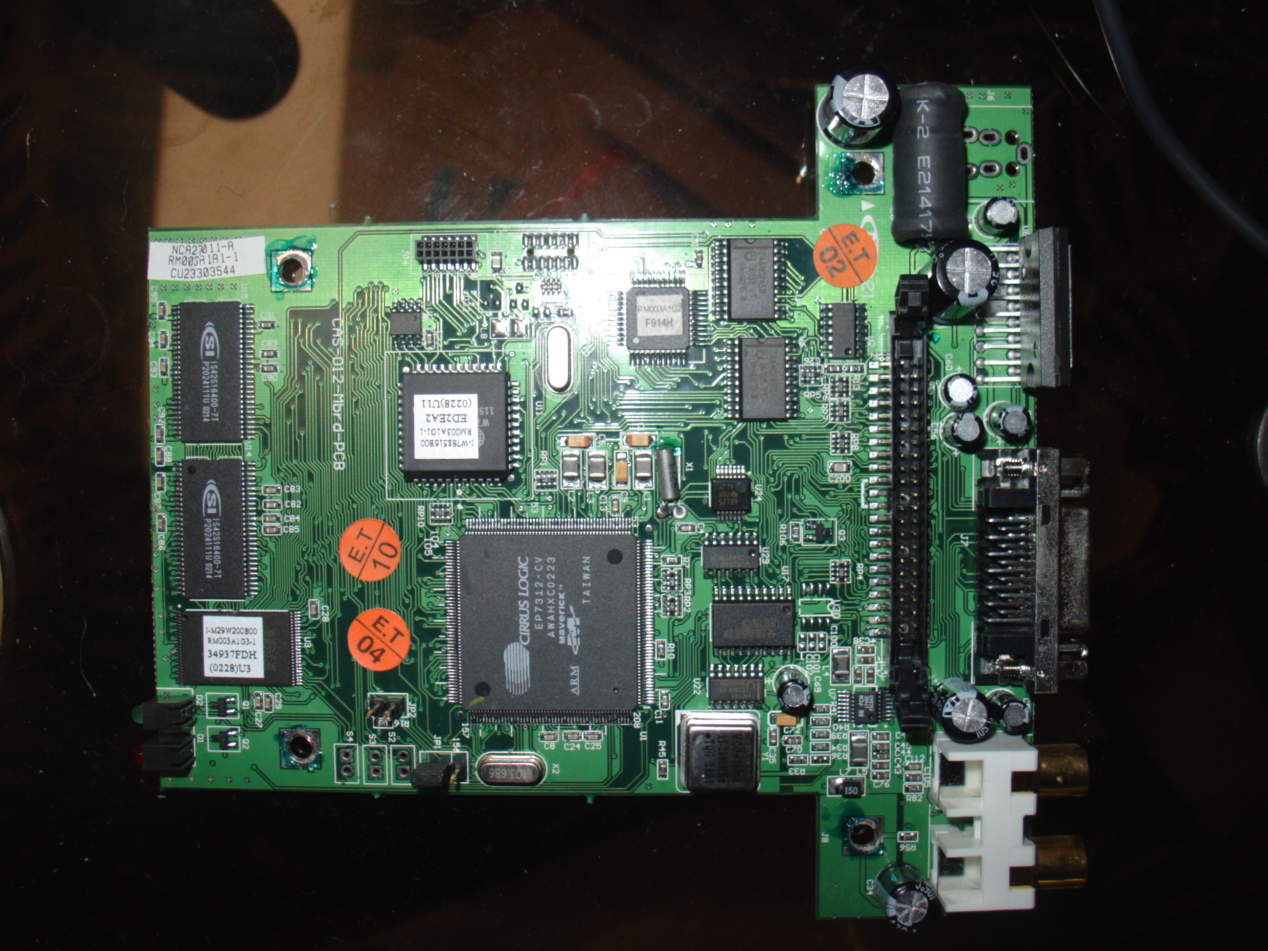
- Connect the wires to JP8 on the CX910 Board or JP4 on the C710 Board as follows
- Yellow (RX) to Pin 5 (TX)
- Blue (TX) to Pin 7 (RX)
- Brown (DCD) to Pin 9 (DCD)
- Orange (CTS) to Pin 13 (CTS)
- Shield (GND) to Pin 14 (GND)
- Plug the USB Cable into your computer and start a shell on the serial port
To start the shell, you can get my working busybox from http://www.phathack.com/busybox.bz2 then use the following to start it on the serial port. See HOWTO: Run Unsigned Code
(If you are using windows you'll need to install the serial port drivers for the USB device.. found http://www.futuredial.com/support/download/prolificdrivers.zip )
/dos/busybox mv /bin/busybox /bin/busybox-old
/dos/busybox ln -s /dos/busybox /bin/busybox
/bin/busybox --install -s
(sh < /dev/ttyS0 > /dev/ttyS0 2> /dev/ttyS0 &)
- This cable needs to have a "bulge" in the middle of it. Radio Shack sells all sorts of Futuredial cables. The cable tested here is described as "LG 1010, 5350, VX1 and VX10" and has product number 170-0783 (above the UPC on the back).
My Installation
NOTE: I had to cut the plastic on the cover to access my DB9 connector, you may want to try putting it vertically on the side away from the RCA plugs
- Obtain:
- Male DB9 Serial Connector
- Female DB9 Serial Connector
- D-Sub hood
- Some solid (not stranded) CAT5 cable
- Soldering iron
- Solder
- Solder the wires from your USB->Serial cable to the male DB9, and mount it in the D-Sub Hood (I used male so nobody will get confused and try to use it for normal serial)
- Strip both ends of the CAT5 cable, and chop off all the white/color wires.
- Strip the solid color wires
- Solder one end of the CAT5 cable to the Female DB9
- Cut hole in PhatBox case, run the wire through hole and connect to JP4/JP8
- Solder the Female DB9 onto case, or screw on
My Pinout
Phatbox Side
JP4 Pinout:
1.....13
2.....14
JP4/JP8 -> CAT5
- Pin5 (TX) -> Green
- Pin7 (RX) -> Blue
- Pin9 (DCD) -> Brown
- Pin13 (CTS) -> Orange
- Pin14 (GND) -> Orange/White
CAT5 -> Female DB9
- Blue -> Pin1
- Green -> Pin4
- Orange/White -> Pin6
- Brown -> Pin8
- Orange -> Pin9
USB/Serial Cable Side
USB Cable -> Male DB9
- Blue (TX) -> Pin1
- Green (DTR) -> Pin2
- Purple (RTS) -> Pin3
- Yellow (RX) -> Pin4
- Red (RI) -> Pin5
- Shield (Ground) -> Pin6
- Empty Pad (DSR) -> Pin7 (This wire does not exist)
- Brown (DCD) -> Pin8
- Orange (CTS) -> Pin9
Pictures


Connection info 115Kbps, 8n1 (flowcontrol?)