Hardware FAQ
This page gathers all kinds of information we know about the PB hardware
CPU (ARM):
- Cirrus Logic EP7312 (Maverick)
- 74MHz
- 2x 16550 UART (serial)
- LCD display controller
- Datasheet
- User's Guide
Microcontroller:
- 8052
- 24MHz
- Headunit interfacing
- Datasheet (Winbond W78E516B)
D/A-Converter:
- Cirrus Logic CS4341
- 16-bit
- Datasheet
IDE interface controller:
Flash ROM
- ST Micro M29W200BB
- 2 MBit
- Automotive grade
- Datasheet
Complex Programmable Logic Device (CPLD)
PCB Layout (Photos):
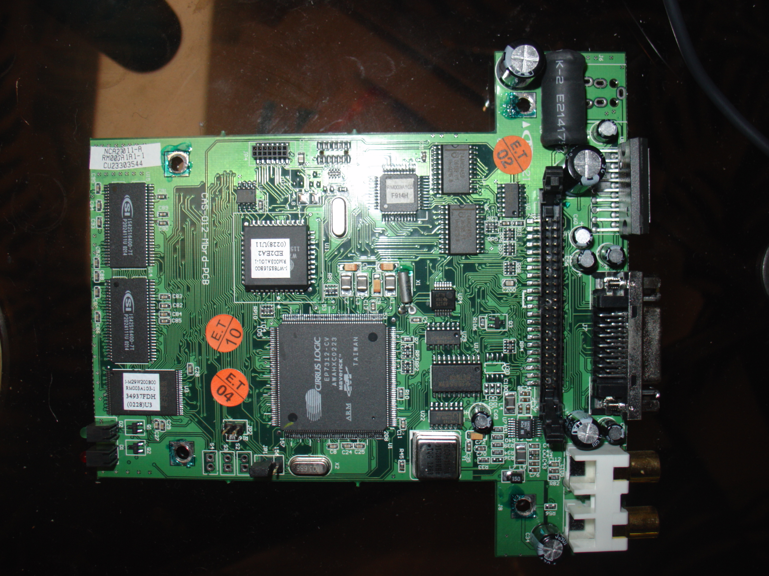
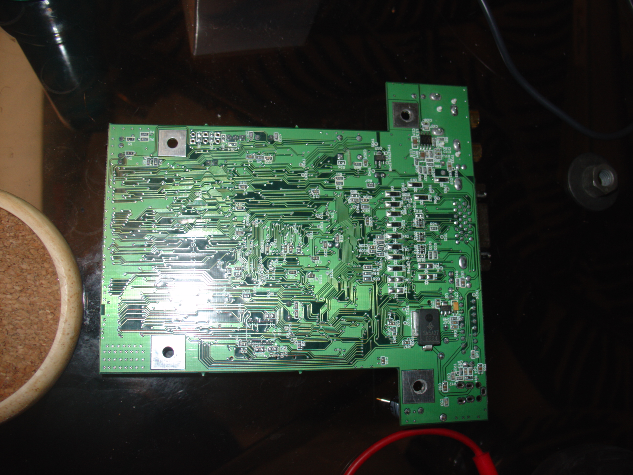
PCB Jumpers:
JP5 -- XILINX 9572XL - JTAG
Pin 6 > 9572XL Pin 48 - TCLK
Pin 8 > 9572XL Pin 83 - TDO
Pin 10 > 9572XL Pin 45 - TDI
Pin 12 > 9572XL Pin 47 - TMS
JP6 -- ARM JTAG (No Connector, just pads)
Pin 3 > 7312 Pin 125 - nTRST
Pin 5 > 7312 Pin 11 - TDI
Pin 7 > 7312 Pin 58 - TMS
Pin 9 > 7312 Pin 90 - TCLK
Pin 11 > 7312 Pin 22 - TDO
JP8 -- ARM UART1 (SERIAL PORT!!!)
Pin 1 > board power
Pin 2 > pin18 - PB2 [GPIO port B]
Pin 3 > some resistor, hard to trace past.
Pin 5 > 7312 Pin 32 - TDX[1]
Pin 7 > 7312 Pin 36 - RXD[1]
Pin 9 > 7312 Pin 37 - DCD
Pin 11 > 7312 Pin 38 - DSR
Pin 13 > 7312 Pin 35 - CTS
JP9 -- XILINX 5032C - JTAG
Pin 6 > 5032C Pin 26 - TCLK
Pin 8 > 5032C Pin 32 - TDO
Pin 10 > 5032C Pin 1 - TDI
Pin 12 > 5032C Pin 7 - TMS
For connections to the JP arrays you can use either: Molex 87332-1420 or DigiKey WM18078-ND
DMS Cartridge:
- 2.5" Notebook harddisk (9.5mm, "rugged" edition)
- FAT32 filesystem
- 2 Partitions (PHTSYS, PHTDATA)